BUNKER PRO 2.0 provides a CAN interface for users to perform secondary development and custom control.
The system follows the CAN 2.0B standard, with a baud rate of 500Kbps.
The data frame format adopts the MOTOROLA format.
Through the external CAN bus interface, users can send commands to control the linear velocity and angular velocity of the chassis.
The BUNKER PRO 2.0 will also provide real-time feedback on its motion status and chassis condition.
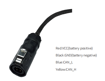
BUNKER PRO 2 ships with the vehicle and provides a male aviation plug as shown in Figure 3.2. The definition of the wires is: yellow is CAN_H, blue is CAN_L, red is the positive power supply, and black is the negative power supply.
<aside> 💡
Note: In the current BUNKER PRO2 version, only the tail interface is open to external expansion interfaces. The power supply in this version can provide a maximum current of 10A.
</aside>
Schematic diagram of aviation plug male connector
Correctly start the chassis of BUNKER PRO 2 mobile robot, and turn on FS RC transmitter. Then, switch to the command control mode, i.e. toggling SWB mode of FS RC transmitter to the top. At this point, BUNKER chassis will accept the command from CAN interface, and the host can also parse the current state of chassis with the real-time data fed back from CAN bus. For the detailed content of protocol, please refer to CAN communication protocol.
The communication protocol includes:
System Status Feedback Frames, Motion Control Feedback Frames, Command Frames, System Status Feedback Frames provide:
Current chassis status, Control mode status, Battery voltage status, Error or fault information
Refer to Table below for the structure of the system status feedback frame.
Bunker Chassis Status Feedback Frame:
| Command Name | System Status Feedback Command | |||
|---|---|---|---|---|
| Sending node | Receiving node | ID | Cycle(ms) | Receive-timeout(ms) |
| Steer-by-wire chassis | Decision-making control unit | 0x211 | 200ms | None |
| Data length | 0x08 | |||
| Position | Function | Data type | Description | |
| byte [0] | Current status of vehicle body | unsigned int8 | 0x00 Normal condition | |
| 0x01 Emergency stop | ||||
| 0x02 System Error | ||||
| byte [1] | Mode control | unsigned int8 | 0x00 Stand by | |
| 0x01 CAN command control | ||||
| 0x03 Remote control | ||||
| byte [2] | ||||
| byte [3] | Battery voltage upper 8 bits Battery voltage lower 8 bits | unsigned int16 | Actual voltage × 10(with an accuracy of 0.1V) | |
| byte [4] | Reserve | - | 0x00 | |
| byte [5] | Failure Information | unsigned int8 | Refer to Table3.2 Failure Information Description | |
| byte [6] | Reserve | - | 0x00 | |
| byte [7] | Count Parity bit (Count) | unsigned int8 | 0~255 Loops counting. Count is incremented once | |
| while single command sent every time |
Description of Failure Information
| Description of Failure Information | ||
|---|---|---|
| Byte | Bit | Description |
| byte [5] | bit [0] | Low-voltage failure |
| bit [1] | Low-voltage warning | |
| bit [2] | Remote control signal lost protection(0: Normal 1: Lost signal) | |
| bit [3] | Reserve, default value 0 | |
| bit [4] | Drive 2 communication failure(0: Normal 1: Failure) | |
| bit [5] | Drive 3 communication failure(0: Normal 1: Failure) | |
| bit [6] | Reserve, default value 0 | |
| bit [7] | Emergency Stop (0: Normal, 1: Emergency Stop Triggered) |