- 16V -45V (Peak 60V) 2 inputs (1 for powering the expansion dock internally, 1 for powering the robotic arm externally)
12V output: 1 output, current output 3A (1 output for external user)
5V output: 1 output, current output 3A (1 output for external user) |
| Gigabit Ethernet Interface | - Total number of interfaces: 2 ports (standard RJ45 interfaces)
Gigabit Ethernet: 1 channel connected to GO2, 1 channel externally connected to the user |
| M8 Aviation Plug Interface
(Gigabit Ethernet + 12V Power) | - Total number of interfaces: 1 port (standard European aviation plug interface)
Gigabit Ethernet: 1 channel for radar-specific interface
Power output: 1 channel 12V/2A output for powering the radar |
| USB-Type A Interface | - Total number of interfaces: 1 USB3.2 Gen2
Supported modes: Only USB host
Power output: Supports 5V/1A
Transfer speed: Supports 10Gbps |
| USB-DP Alt Mode Type-C Full-Featured Interface (USB+DP) | - Total number of interfaces: 1 Type-C
Supported modes: Supports USB host or DP Alternative Mode
USB: Supports USB2.0
DP: Supports DP1.4
Power output: Supports 5V/3A |
| USB-Type-C Interface | - Total number of interfaces: 1 Type-C
Interface type: Supports USB3.2 Gen2
Power output: Supports 5V/2A |
| GH1.25-4PIN Interface
(Gigabit Ethernet) | - Total number of interfaces: 1 port
Gigabit Ethernet: 1 channel externally connected to the user |
Install additional equipment
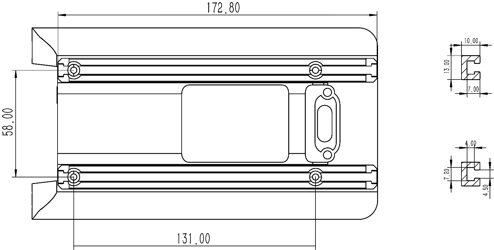
Rail size
Install expansion dock
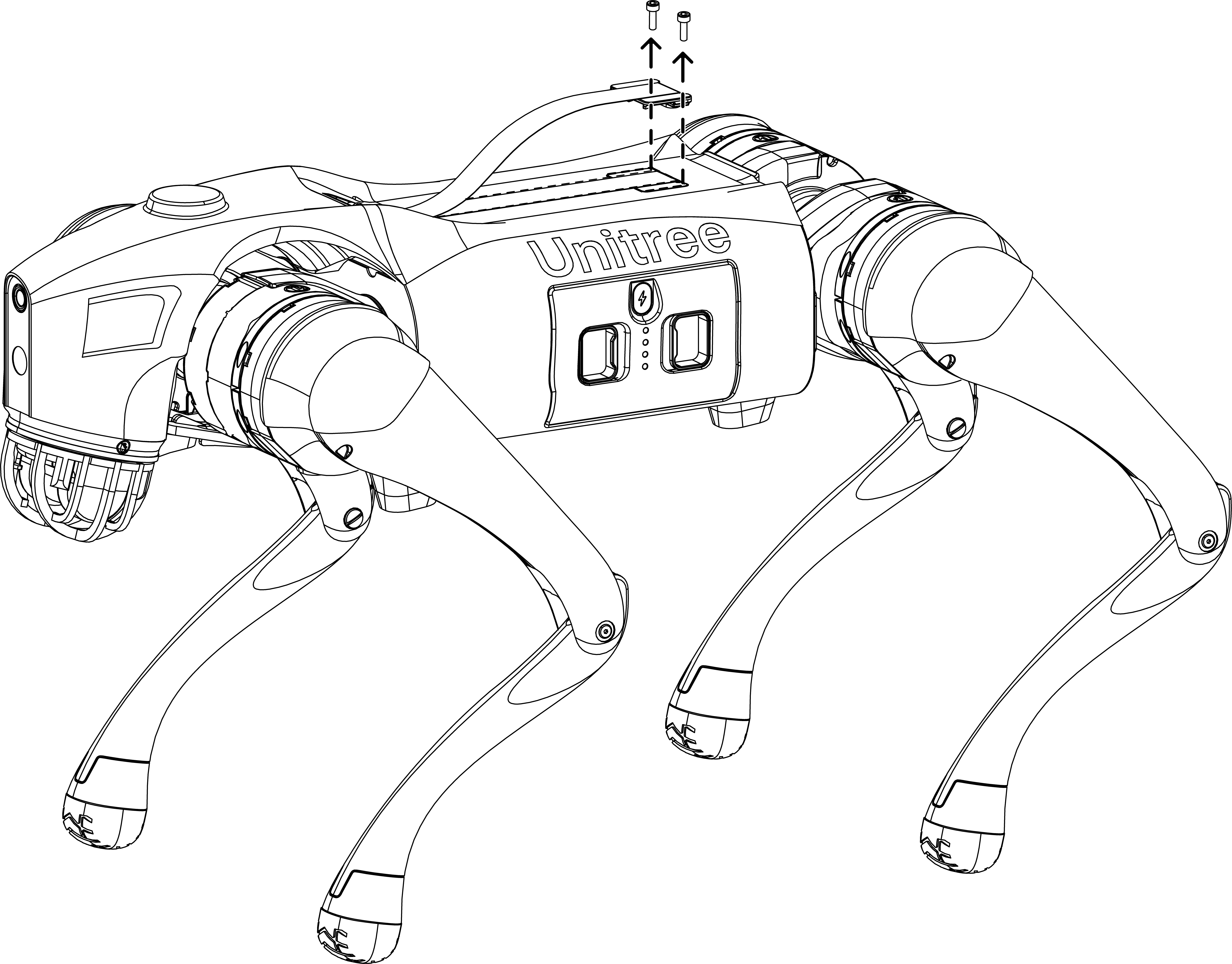
Use the hex L-shaped wrench to remove the screws securing the back cover of the Go2, then open the back cover as shown in the figure below.
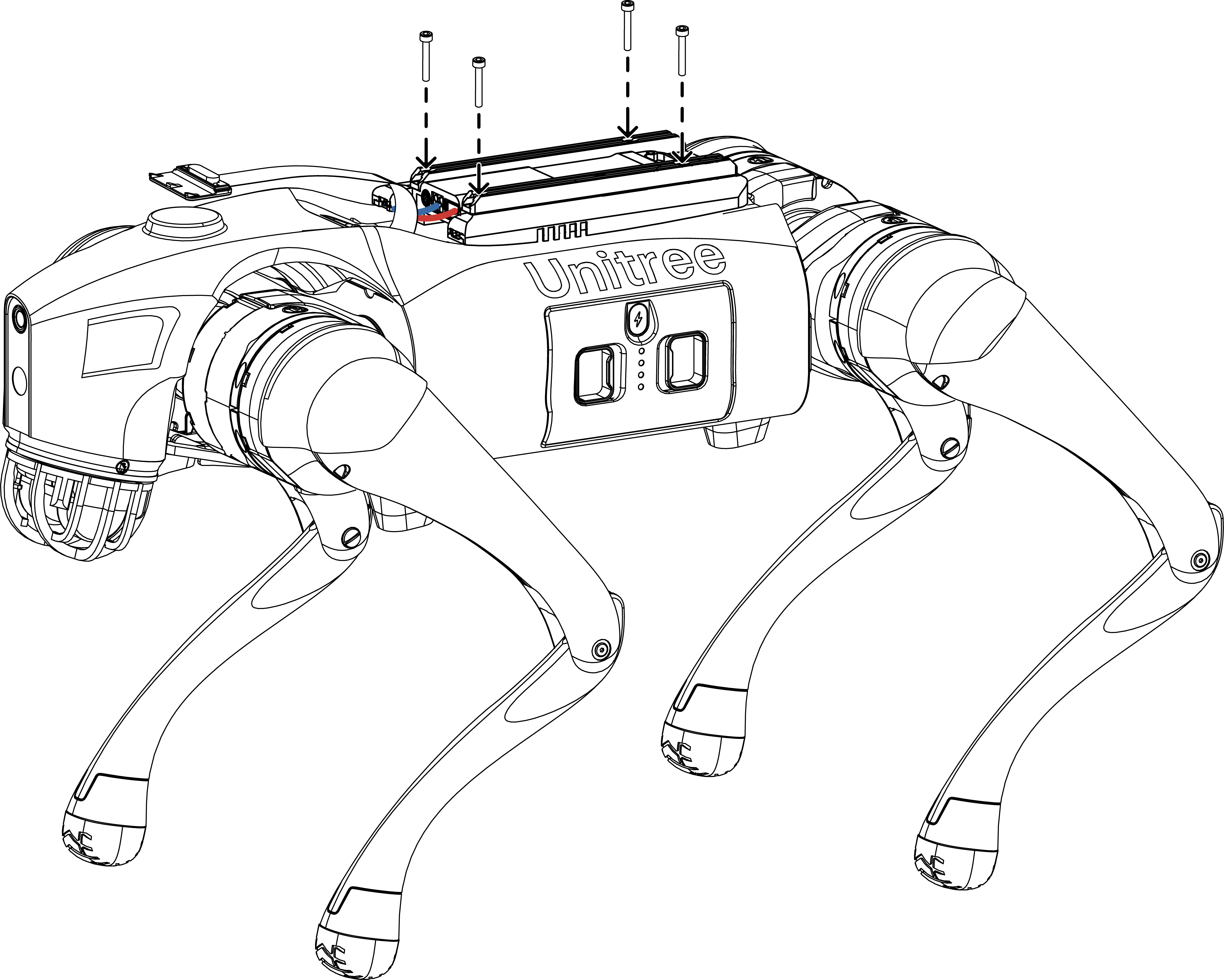
Connect the power and Ethernet ports of the main body to the high-performance module's power and Ethernet ports, then secure the cables in the expansion dock cable groove, as shown in the figure below.
Use screws M3×50 to secure the expansion dock to the back of the Go2, as shown in the figure below.
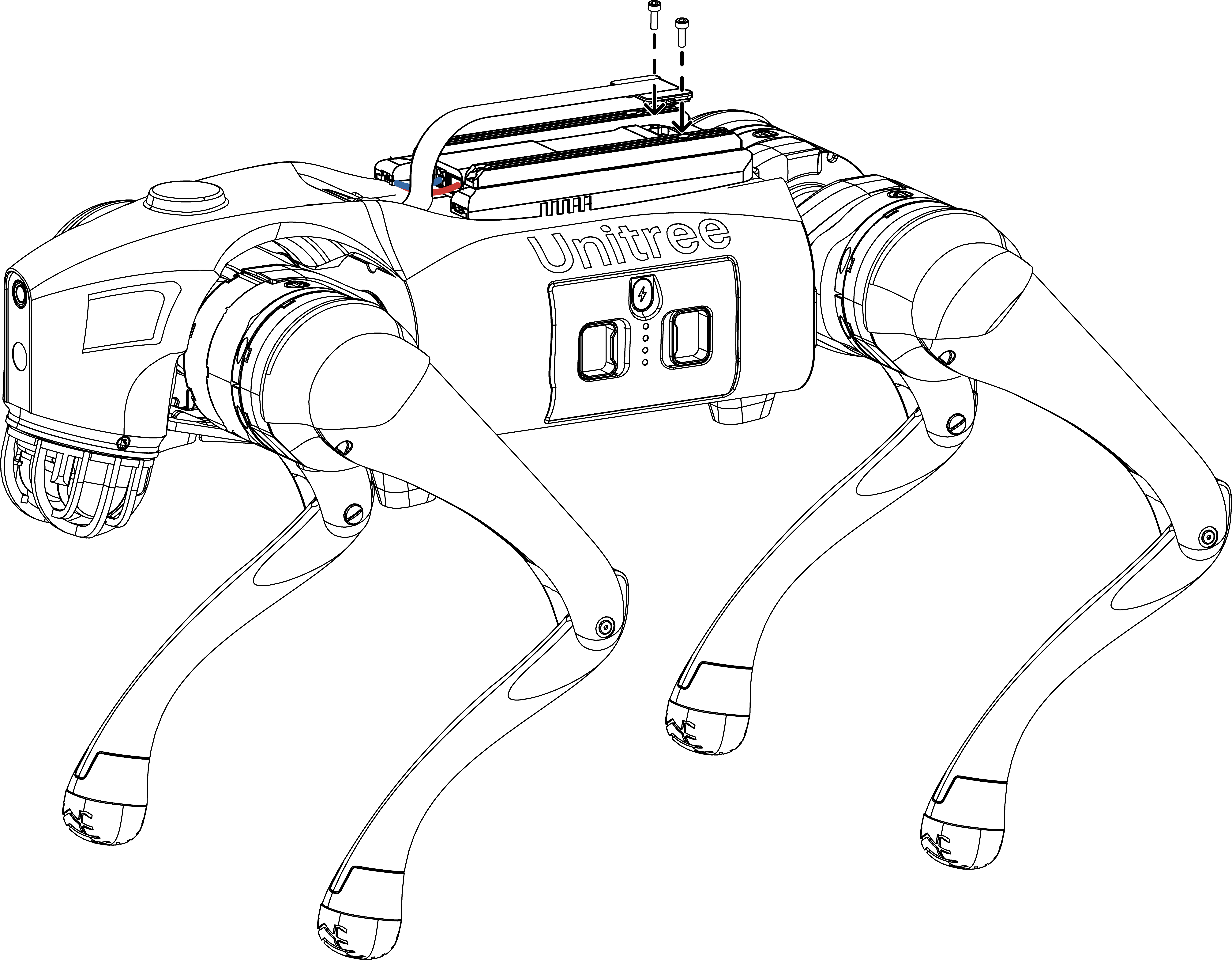
Secure the back cover of the main body to the expansion dock cover, as shown in the figure below.